
This dissertation aims to ascertain to which degree a so-called Faraday Rotation Magnetometer (FRM) may be used to measure very localised electrical currents or magnetisations.
Electrical currents as well as magnetisations cause magnetic fields. Within certain materials these fields cause the rotation of the polarisation plane of linearly polarised light in accordance with the Faraday effect. Here, the material-dependant sensitivity of the rotational angle w.r.t. an external magnetic field is described by the so-called Verdet constant. The rotated light subsequently passes a linear polarisation filter where different relative angles between the polarisation plane and the polariser result in different transmitted intensities. These intensities, in turn, can relatively easily be measured with a camera. Knowing the intensities then allows the calculation of the rotational angle and, therefore, the magnetic excitation field and the estimation of its causes, i.e. electrical currents or magnetisations.
Figure 1 shows such a FRM, which is centred around a material with an extremely high Verdet constant – a so-called Faraday crystal. It allows the non-destructive and contactless probing of highly localised magnetic fields and their causes. In this dissertation magnetic microstructures with structure sizes in the order of magnitude of 10 µm are analysed. Such structures may be used to encode information on the security thread of banknotes. The scope of FRMs for such measurements w.r.t. high spatial and temporal resolutions is determined. A particular focus is put on finding the limits of quantitative measurements. To this end, the most critical components light source, Faraday crystal, and camera will be thoroughly characterised and, if need be, replaced. The influence of inherent errors, such as the ferromagnetic behaviour of the crystal seen in figure 2, need to be dealt with using digital signal processing methods.
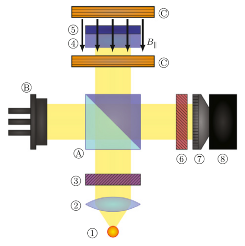 Figure 1: Schematic of the utilised Faraday Rotation Magnetometer (1.: LED, 2: lense, 3: polariser, 4: Faraday crystal, 5: mirror coating, 6: analyser, 7: objective, 8: camera, A: beam splitter, B: photodiode, C: Helmholtz coils)
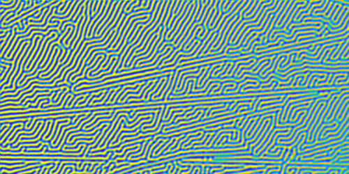 Figure 2: Inherent magnetic domain structure of the Faraday crystal remains even at 0 kA/m excitation and is superposed to the signal carrying the wanted information.
Johannes Kepler University Linz
Altenberger Straße 69
4040 Linz, Austria
 Go to JKU Homepage
